|
Same as
|
option copies typical girder parameters values from one span to another. |
|
Number of girders
|
Number of steel girders used for the composite bridge. |
|
Girder type
|
Sectional shape of the steel girders used. |
|
Girder ID
|
Select the primary member id to be used (only I-shape is allowed). By right clicking on the arrow, add/edit options will be available and send you to profiles definition menu where you can add new profiles or modify existing ones. |
|
Alignment reference
|
Typical points in cross-sections to be used for measuring distances between different parts or members; we have 5 options for selection and showed in a picture next to it:
-
TopFlange
-
TopWeb
-
CenterWeb
-
BottomWeb
- BottomFlange.
|
|
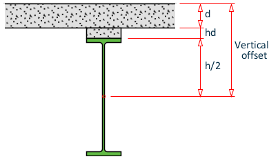
Vertical offset
|
Vertical distance between the reference point of the slab and the reference point on the girder, point that was selected in alignment reference field. |
|
Roadway
|
After the roadway template is assigned for a certain span a series of options described below must be selected depending on the required deck slab design. |
Deck bottom surface: parallel to top surface /Straight |
Girder positioning: Normal to deck bottom surface/ Vertical |
Pier cap top surface: Horizontal/ Parallel to deck surface |